The RC Geek Blog
By: Chris Wolfe
Fiberglassing and Hinges…now we’re getting somewhere!
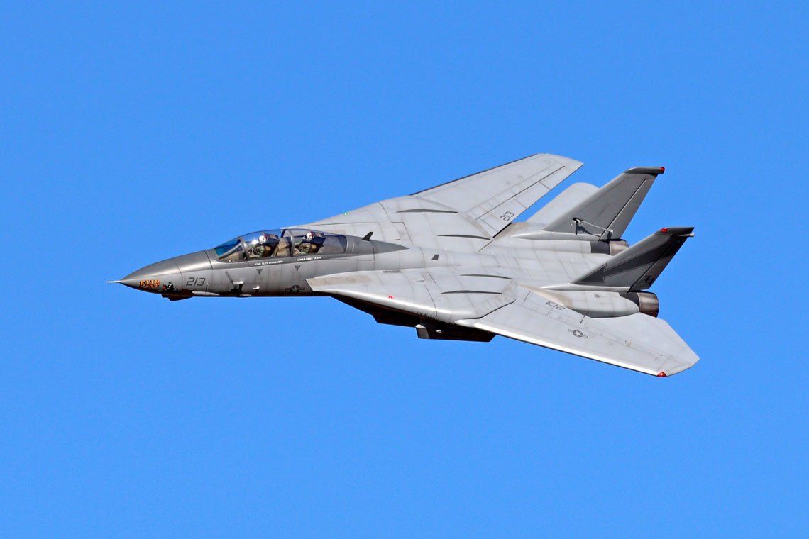
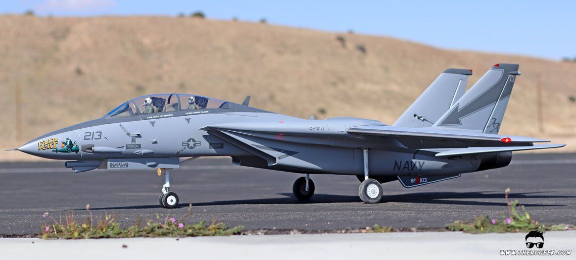
 With the dorsal and rudder shaped, the next step is fiberglassing and hinging each of the parts. I didn’t take many pictures during the glassing process (performed this before starting this blog), but I will talk through it a little bit. When I get to fiberglassing the wings, I plan to make a complete tutorial video. The pic to the left is ultimately what we are striving for…
Some Notes on Fiberglassing
Now, I typically don’t hinge control surfaces until after glassing. I’ve done it both ways (hinging before and after glassing) and have found hinging after glassing is definitely my preference. The reason for this is that when I make the slots in the control surfaces to receive the hinges, I can get much cleaner and crisper corners since the glass hardens the wood. Otherwise, the balsa can crush in around the slot and it doesn’t come out as cleanly. In terms of glassing, I use 3/4 oz fiberglass cloth and Pacer Z-Poxy Finishing Resin finishing epoxy resin to apply the glass. The fiberglass is cut out around the surface allowing significant overlap and laid flat onto the surface dry (important!). From there, I mix up the Z-Poxy Resin as directed (50/50 mix on a scale) in a paper cup. I drizzle it onto the dry fibreglass in the center of the surface and then wet out the glass (while on the surface) using an old credit card or something similar as a squeegee. I wet out the glass from the center out towards the edges until the entire surface is covered. There should be no pooling of resin once done, so make sure to squeegee any excess as this is just extra weight otherwise. For the leading edge, it’s important to get some overlap around so that you get full coverage when glassing the other side (at least 3/4 coverage around the LE). This also adds some additional hardness since if done right, you will get a double layer of fiberglass over the LE. For the trailing edge, the glass should be wetted to about 1/4-1/2″ past the trailing edge of the actual surface. This is again for full coverage, but also so that when the opposite side is glassed, it creates a stiff trailing edge that once cured can be sanded to a nice sharp point at about 1/32-1/16″ past the wood trailing edge.
Dorsal glassed and curing
Rudder glassed and curing
Offset Rudder Hinge
 With the surfaces fiberglassed, it is then a matter of hinging the rudder. The Skyray has a pretty distinct rudder setup having large hinge cutouts while also being split into an upper yaw damper and lower rudder. The cutout outlines were first transferred to the rudder along with the rudder/yaw damper split line using the plans as well as my reference material ( see this post for a discussion of that
). The cutouts were made first using a razor saw as well as an Xacto knife with a metal straight edge. The key is to ensure everything is as desired before making any cuts at all and then in the process of cutting taking time to ensure straight cuts. Any areas where I overcut or weren’t quite square, I used USC Icing
(two part filler like bondo) to fill in. In the case for the large cutout, I didn’t quite get the cuts square, so I took a piece of 1/64″ ply, applied a piece of packing tape to it and cut it on the back side (not penetrating through the tape) so that it could be folded into the shape of the cutout. I then tack glued it into the opening and filled with the Icing any open spaces to get clean corners and a square opening. The beauty is that the Icing will not stick to the packing tape once cured completely.
All surfaces cut, ready for hinging
Once happy with the hinge cutouts, the rudder was split into a top and bottom in much the same way using an Xacto with a straight edge and a razor saw to cut through the 1/64″ ply trailing edge stiffener. The end caps were made simply by lightly wetting a paper towel with some lacquer thinner, touching the foam to lightly melt a little of it on the ends of the rudders, and then using a balsa wood filler to fill in the space (they can also be capped with 1/64″ plywood as well but requires removal of 1/64″ material on each end first).
 The Skyray has an offset hinge on the rudder, so before starting on hinging the surface, it was necessary to plot out where the hinge location should be. The plans and documentation resources were referred to do this and then the location was plotted on the rudder. The dorsal hinge supports were plotted also and made out of plywood of the appropriate thicknesses to achieve a scale look for each hinge bracket. A 3/32″ aluminum tube was embedded through the hinge location on each of the supports. This in turn required embedding 3/32″ alum tube in the rudder parts as well. This had to be done by slotting the LE of the rudder the appropriate width, embedding the aluminum tube into the rudder along the hinge line and then replacing the removed material from the LE and resanding it to shape. The bare wood was then sealed simply by brushing some mixed Z-Poxy over the exposed wood and then lightly sanding it once cured. To mount the hinge brackets, it required cutting slots in the rudder spar at the appropriate locations to receive the plywood hinge supports. With all of this done, the rudder hinge is then created by placing a 1/16″ wire through the tubing in the rudder and hinge brackets. With everything aligned properly, you get an extremely smooth hinge that actuates representatively to the full size aircraft. The wire will be held in place with a cap over the middle hinge support (upper yaw damper will be fixed) once everything is ready for final install.
Installing the Torque Rod
The last item of business is installing the rudder torque rod which was done by removing the foam in the area of the torque rod and installing a balsa block. From there, a slot was cut in the leading edge of the rudder to allow for the torque rod to be inset into the rudder. It is aligned so that the center of the torque rod lines up as an extension of the rudder hinge line (very important). This minimizes any lateral movement once everything installed which alleviates any biases that could be imparted onto the rudder servo and linkage assembly.
Next time we’ll talk about detailing and finishing our rudder and dorsal assembly. That’s where the hard work and prep really starts to pop!
The post How to Build an RC Jet – Part 5 appeared first on The RC Geek.
The RC Geek Blog is your place to learn about all aspects of the RC hobby. Learn to build, design, drive or fly that RC project you’ve always wanted to build, but have been intimidated to try. This blog is here to help you on your journey and provide tips and tricks as you go! My hope is to inspire builders both experienced and new! So, welcome, please look around, it’s an exciting beginning! I’m currently documenting my latest competition scale RC jet build, a Mark Frankel F4D Skyray, along with some other fun tips and videos. If you can’t find what you’re looking for on this front page, click on any of the categories to the right and it will show just posts related to those categories. Please feel free to add comments and/or contact me directly if you have questions, I’m here to help! And don’t forget to check out my YouTube Channel, I post new videos every week!
Subscribe To Our Blog Now
